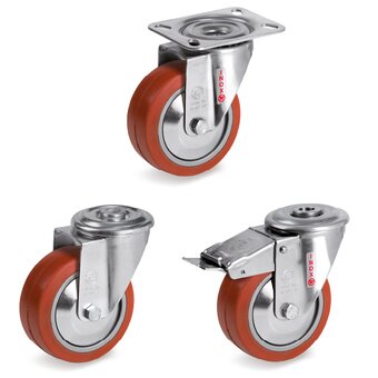
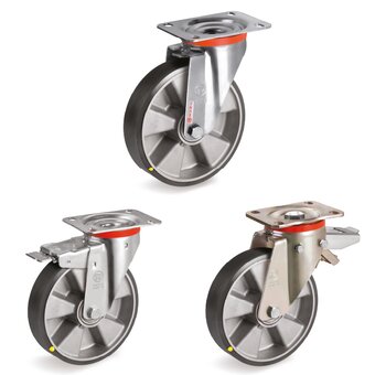
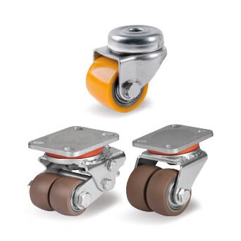
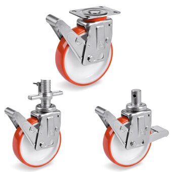
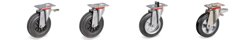
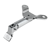
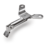
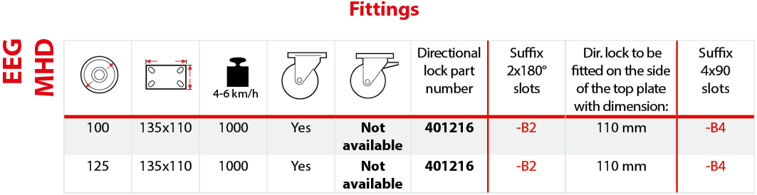
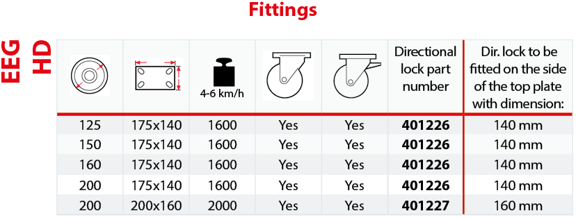
Directional lock for EEG MHD brackets (item nr 401216) and EEG HD brackets (item nr 401226 for 175x140 mm top plate) (item nr 401227 for 200x160 mm top plate)
|
|
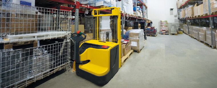
Designed for assembly on the top plate’s short side, it consists of galvanised steel parts and is suitable for trolleys subject to mechanical towing at speeds up to 16 km/h on indoor and outdoor floors (asphalt, cement).
Easy to engage by self-clicking into position.
Specifications:
- it is fitted to the top plate of a castor by using the same fixing bolts which secure the bracket to the trolley
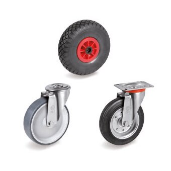
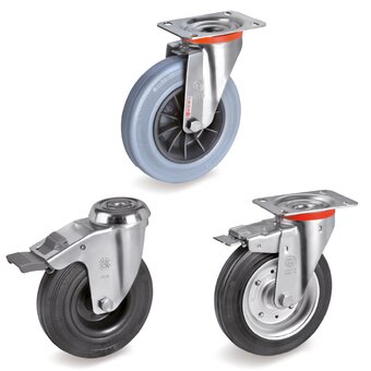
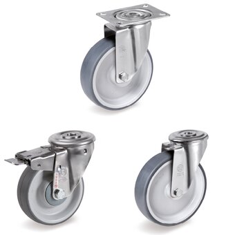
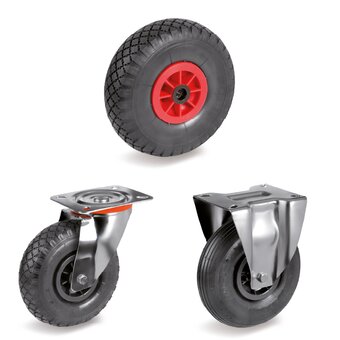
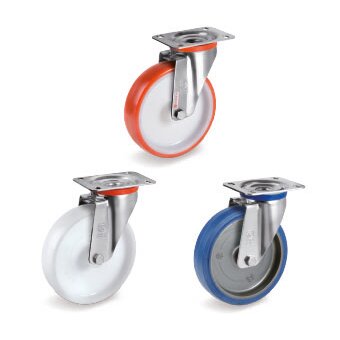
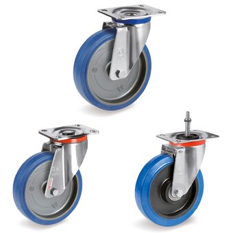
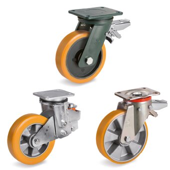
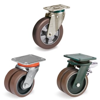
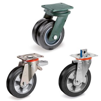
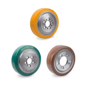
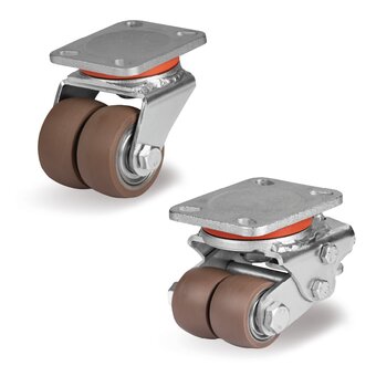
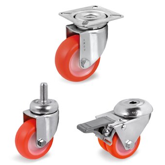
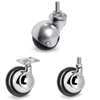
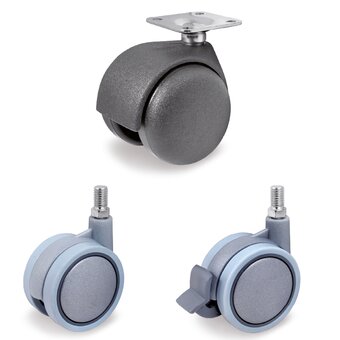
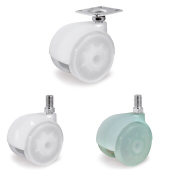
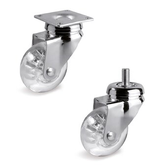
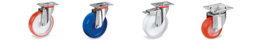
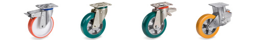
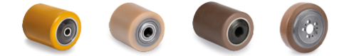
- it can be purchased as an accessory and combined with EEG MHD twin electrowelded castors with 100 - 125 mm diametres, and with EEG HD twin electrowelded castors with 125 -200 mm diametres;
- It can only be fitted with brackets designed for 2 (180°) or 4 (90°) locking positions for the EEG MHD brackets, and only with 4 (90°) locking positions for the EEG HD bracktes.
|
|
|
|
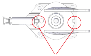
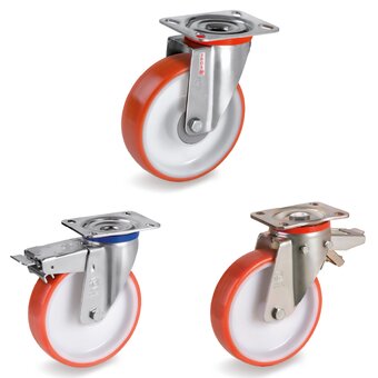
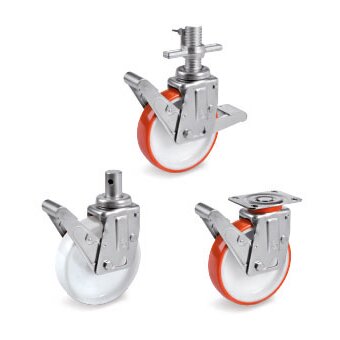
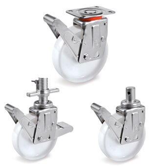
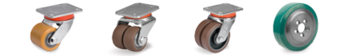
Bracket with 2 slots at 180°
|
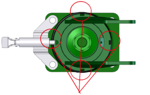
Bracket with 4 slots at 90°
|
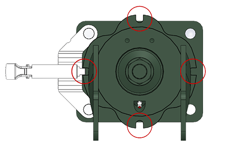
Bracket with 4 slots at 90°
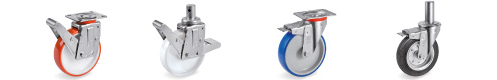
The directional lock for electrowelded castors can be assembled with brackets with appropriate slots.
To order castors configured with slots, please add the above specified suffix to the part number of the complete castor.
Example: to order the part number 628314 with 2 slots, it is necessary to show the part number 628314B2.
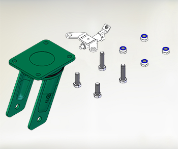
SCHEME OF ASSEMBLY
PREPARATION
4 M10 bolt and 4 M10 nuts are required for dir. lock 401216; M14 bolt and nuts are required for dir. lock 401217-401226 and M16 bolt and nuts are required for dir. lock 401227. Self-locking nuts and 8.8 bolt strenght are recommended. The length of the bolt depends on the characteristics of the trolley the castors have to be fitted onto (it should be usually longer than 40mm).
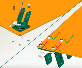
INSTALLATION
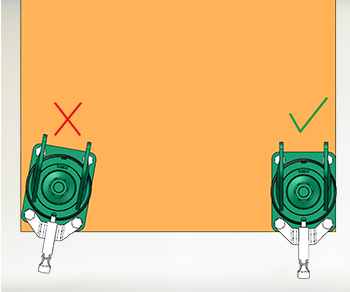
The directional lock and the castor have to bee positioned and subsequently fastened as per the exemplification in the adjacent picture (note: the picture shows the bracket without the wheel for handiness of the image only).
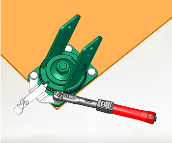
FASTENING
The bolt has to protrude through the nut by al least 3 threads.
The proper tightening of the bolts has to be verified by a torque wrench. The recommended tightening torque of a self-locking nut is of 48Nm for dir. lock 401216, of 130Nm for dir. lock 401217-401226 and of 205Nm for dir. lock 401227.
FINAL CHECK
Make sure that the directional lock engages properly into the slots of the bracket and that the castors are aligned to the direction of movement of the trolley once the the directional lock is applied.
'%3e%3cg id='Final-Copy-2_2_' transform='translate(1275.000000, 200.000000)'%3e%3cpath class='st0' d='M7.4,12.8h6.8l3.1-11.6H7.4C4.2,1.2,1.6,3.8,1.6,7S4.2,12.8,7.4,12.8z'/%3e%3c/g%3e%3c/g%3e%3c/g%3e%3cg id='final---dec.11-2020'%3e%3cg id='_x30_208-our-toggle' transform='translate(-1275.000000, -200.000000)'%3e%3cg id='Final-Copy-2' transform='translate(1275.000000, 200.000000)'%3e%3cpath class='st1' d='M22.6,0H7.4c-3.9,0-7,3.1-7,7s3.1,7,7,7h15.2c3.9,0,7-3.1,7-7S26.4,0,22.6,0z M1.6,7c0-3.2,2.6-5.8,5.8-5.8 h9.9l-3.1,11.6H7.4C4.2,12.8,1.6,10.2,1.6,7z'/%3e%3cpath id='x' class='st2' d='M24.6,4c0.2,0.2,0.2,0.6,0,0.8l0,0L22.5,7l2.2,2.2c0.2,0.2,0.2,0.6,0,0.8c-0.2,0.2-0.6,0.2-0.8,0 l0,0l-2.2-2.2L19.5,10c-0.2,0.2-0.6,0.2-0.8,0c-0.2-0.2-0.2-0.6,0-0.8l0,0L20.8,7l-2.2-2.2c-0.2-0.2-0.2-0.6,0-0.8 c0.2-0.2,0.6-0.2,0.8,0l0,0l2.2,2.2L23.8,4C24,3.8,24.4,3.8,24.6,4z'/%3e%3cpath id='y' class='st3' d='M12.7,4.1c0.2,0.2,0.3,0.6,0.1,0.8l0,0L8.6,9.8C8.5,9.9,8.4,10,8.3,10c-0.2,0.1-0.5,0.1-0.7-0.1l0,0 L5.4,7.7c-0.2-0.2-0.2-0.6,0-0.8c0.2-0.2,0.6-0.2,0.8,0l0,0L8,8.6l3.8-4.5C12,3.9,12.4,3.9,12.7,4.1z'/%3e%3c/g%3e%3c/g%3e%3c/g%3e%3c/g%3e%3c/svg%3e) Le tue preferenze relative alla privacy
Le tue preferenze relative alla privacy