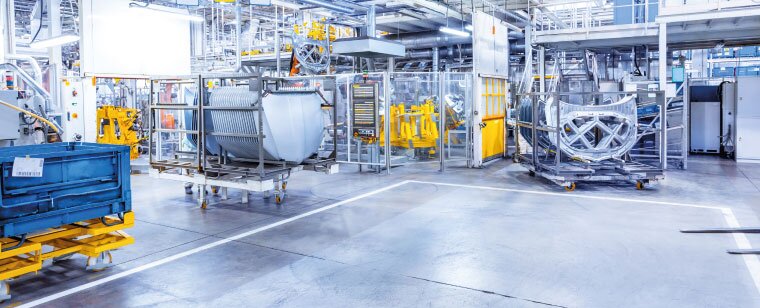
Wheels and castors for food processing industries
'%3e%3cg id='Final-Copy-2_2_' transform='translate(1275.000000, 200.000000)'%3e%3cpath class='st0' d='M7.4,12.8h6.8l3.1-11.6H7.4C4.2,1.2,1.6,3.8,1.6,7S4.2,12.8,7.4,12.8z'/%3e%3c/g%3e%3c/g%3e%3c/g%3e%3cg id='final---dec.11-2020'%3e%3cg id='_x30_208-our-toggle' transform='translate(-1275.000000, -200.000000)'%3e%3cg id='Final-Copy-2' transform='translate(1275.000000, 200.000000)'%3e%3cpath class='st1' d='M22.6,0H7.4c-3.9,0-7,3.1-7,7s3.1,7,7,7h15.2c3.9,0,7-3.1,7-7S26.4,0,22.6,0z M1.6,7c0-3.2,2.6-5.8,5.8-5.8 h9.9l-3.1,11.6H7.4C4.2,12.8,1.6,10.2,1.6,7z'/%3e%3cpath id='x' class='st2' d='M24.6,4c0.2,0.2,0.2,0.6,0,0.8l0,0L22.5,7l2.2,2.2c0.2,0.2,0.2,0.6,0,0.8c-0.2,0.2-0.6,0.2-0.8,0 l0,0l-2.2-2.2L19.5,10c-0.2,0.2-0.6,0.2-0.8,0c-0.2-0.2-0.2-0.6,0-0.8l0,0L20.8,7l-2.2-2.2c-0.2-0.2-0.2-0.6,0-0.8 c0.2-0.2,0.6-0.2,0.8,0l0,0l2.2,2.2L23.8,4C24,3.8,24.4,3.8,24.6,4z'/%3e%3cpath id='y' class='st3' d='M12.7,4.1c0.2,0.2,0.3,0.6,0.1,0.8l0,0L8.6,9.8C8.5,9.9,8.4,10,8.3,10c-0.2,0.1-0.5,0.1-0.7-0.1l0,0 L5.4,7.7c-0.2-0.2-0.2-0.6,0-0.8c0.2-0.2,0.6-0.2,0.8,0l0,0L8,8.6l3.8-4.5C12,3.9,12.4,3.9,12.7,4.1z'/%3e%3c/g%3e%3c/g%3e%3c/g%3e%3c/g%3e%3c/svg%3e) Le tue preferenze relative alla privacy
Le tue preferenze relative alla privacy
Wheels and castors for food processing industries
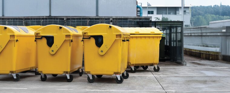
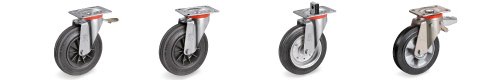
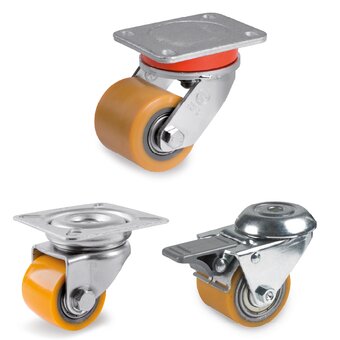
Wheels, castors and accessories for trolleys used in internal industrial logistics
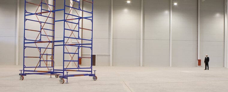
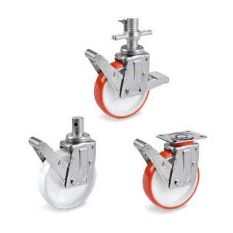
Castors for scaffoldings
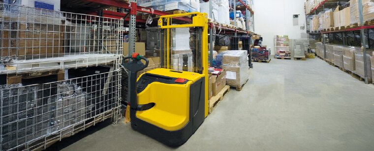
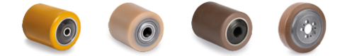
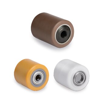
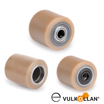
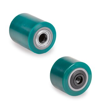
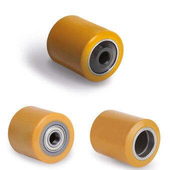
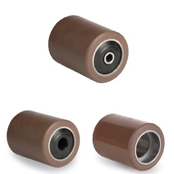
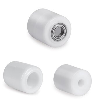
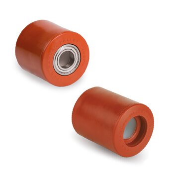
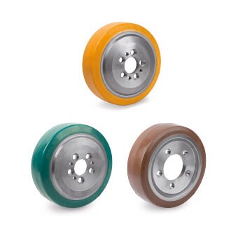
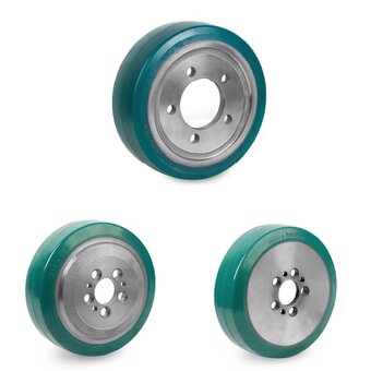
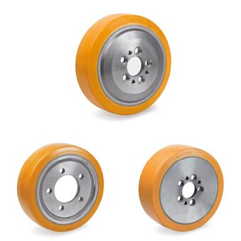
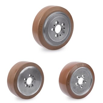
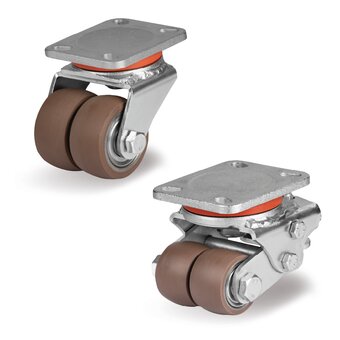
Rollers, drive wheels and stabilizer wheels for pallet trucks
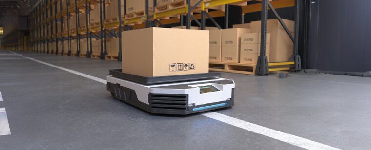
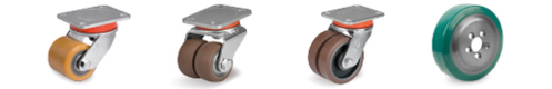
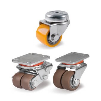
Compact castors for AGVs, AMRs and robotic systems
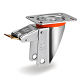 |
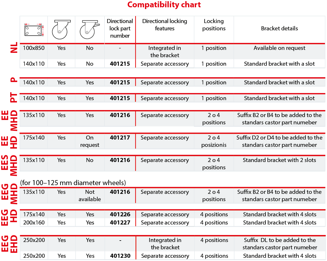
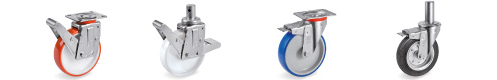
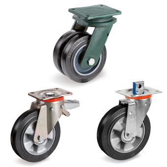
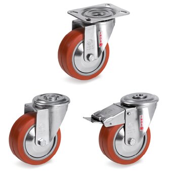
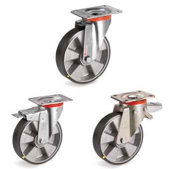
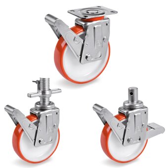
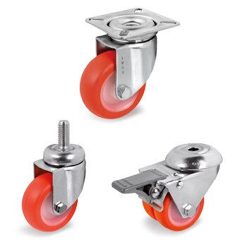
NL bracket with integreted directional lockdiameter from 80 to 125 mm - 100x85 mm top plate |
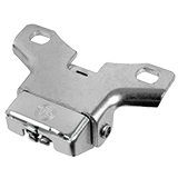 |
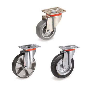
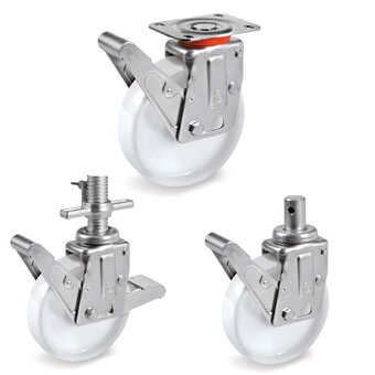
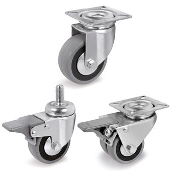
Directional lock for NL- P- PT bracketsdiameter from 125 to 200 mm - 140x110 mm top plate (item nr 401215) |
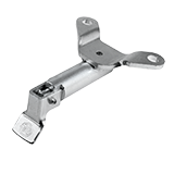 |
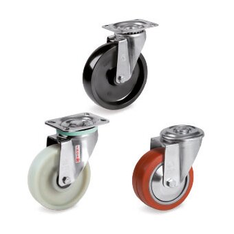
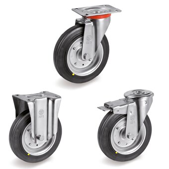
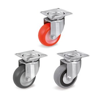
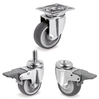
Directional lock for EE MHD bracketsdiameter from 100 to 250 - 135x110 top plate (item nr401216) |
Directional lock for EES MHD bracketsdiameter from 150 to 250 - 135x110 top plate (item nr401216) |
|
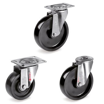
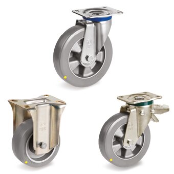
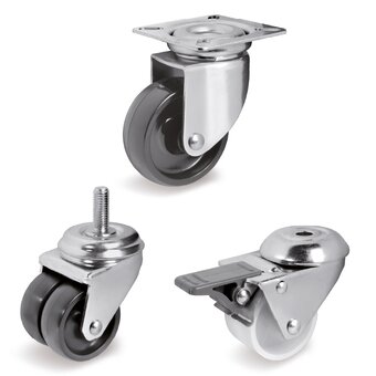
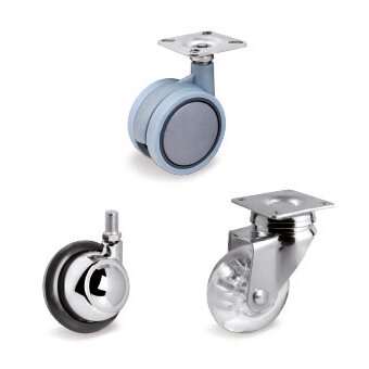
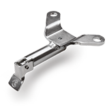
Directional lock for EE HD bracketsdiameter from 150 to 300 mm - 175x140 top plate (item nr401217) |
|
Directional lock for EEG MHD bracketsdiameter from 100 to 125 mm - 135x110 top plate (item nr401216) |
|
 |
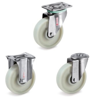
Directional lock for EEG HD bracketsdiameter from 125 to 200 mm - 175x140 mm top plate (item nr401226) - 200x160 mm top plate (item nr401227) |
 |
Directional lock for EEG EHD bracketsdiameter from 200 to 300 mm - 250x200 top plate (item nr 401230) |